I’m back writing another blog post! I am writing this blog post due to the interesting challenge our robot design has presented us in the code (Thanks build team). This blog post will be a bit different as I will be writing about my thought process and how I came to the conclusion of the code I wrote.
The Problem#
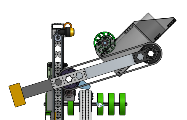
Our robot this year has an elevator and an arm with an intake at the end of the arm. The elevator and arm both have a motor and encoder, allowing the code to accurately position and control the height and angle the resulting angle of the intake using PID. The intake’s rotation is locked to the elevator tower, so the intake is at a permanent 45 degree angle. The arm can rotate around over the top to get from one side of the tower to another. However, if the elevator is to low then the intake can hit the elevator tower, giving us our dilemma. How can we effectively control the height and angle of the arm over time to get to a desired position is the least amount of time?
First Ideas#
When I first saw the problem, I though of a simple solution. I would keep an enum of what side it was on and then if we needed to switch sides we would just move the elevator to a certain height and then rotate the arm over the top. This would work, but it would be very slow and not very efficient and be tippy. Another idea I had was to map out a curve where the elevator would have to be at a certain height for the arm to be at certain angles. This would work, but it would be very hard to implement and would not be very flexible while also being hard to be in between enabling curve control or regular control. However, this idea gave me other ideas like only picturing it in a 2D plane and writing code to only deal with it in a 2D scenario. At the end of the meeting I had a few ideas, but nothing concrete. I decided to go home and write a simulation to test my ideas.
The Simulation#
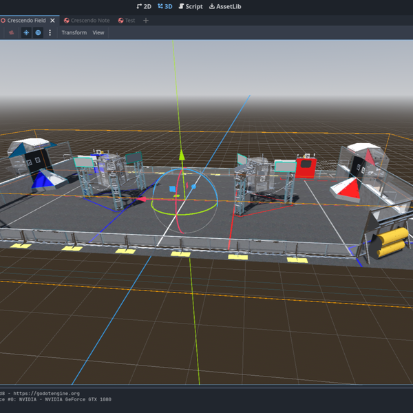
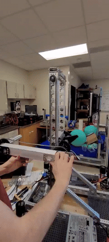
I decided to write the simulation in Bevy as I was familiar with rust and I wanted to learn more about Bevy and its ECS architecture. I also chose bevy due to its Rapier Physics Plugin which is well maintained, fast, and easy to use. I started by making a simple 2d scene with the rapier debug renderer and writing a python script to easily convert our CAD dimensions (in Inches) to bevy/rapier units (in Pixels). After I had the basics created, I started making the actual simulation. I made the elevator tower as a static object and then made the elevator cariage/pivot, arm, intake mount/pivot, and intake as dynamic rigid bodies. I made the intake pivot angle locked so it would always be at a 45 degree angle. I connected all of the pieces with Rapier joints with limits. I also set the gravity of all the objects to 0 to simulate constant force springs and counterweights. Then, I added a simple control script to apply a force to the intake to move twards the mouse position. After a few hours of work, I had a working simulation that looked like this:
I still had no idea how to control the position of the arm, but I had a good base to work off of. I put it on github and created some github actions to test and build it on every push. I decided to sleep on it and come back to it later.
More Simulation Work#
The next day I came back to the simulation and started working on simulating the motors in the code. Luckily, Rapier supports motors on joints. After looking at the docs I added them to be controlled by code I wrote. Before that, I separated the simulation into two modes, code controlled and mouse controlled. This allowed me to easily switch between the two modes and test the motors. I then set up code control mode with an enum of preset heights and angles to switch between. I just set the motor position target based on the selected target. As expected, when we try to switch sides, it would hit the elevator body. Using this simulation I thought of an idea to solve this problem.
The Solution#
The solution is simple in theory but gets more complex the more you look at it. Here is what we are given:
- We can control the height and angle of the arm via PID
- We know the height and angle of the arm and the arm length
- Given the height, angle, and arm length, we can get the 2D position of the intake
- Given a 2D position, we can get the angle and height of the arm via inverse kinematics
- Known dimensions of every part and their ranges of motion
Given this, I though of a simple solution: A*. Because we have the known dimensions and ranges of motion, we can create a collision grid to tell us if a position is valid or not. After we have this generated grid, we can then follow these steps to move from point A (current position) to point B (desired position):
- Get the 2D position of point A and point B
- Get the optimal path using A* on the 2D grid
- For each point in the path, get the height and angle of the arm using inverse kinematics
- Constantly update the target height and angle of the arm to follow the path
- Arrive at point B
This solution is simple in theory, but gets more complex when you look at the details. For example, how do we generate the grid? How do we efficiently run A*? How does inverse kinematics work? I will go over these questions in the next sections.
Generating the Grid#
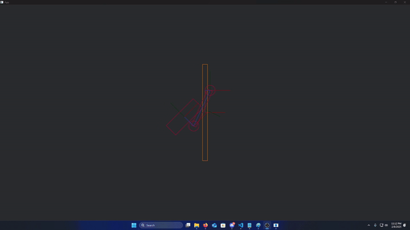
To generate the grid, I used a simple brute force method. I iterated over every point in the grid and checked if it was valid or not. Because I already made the simulation, I made the simulation code into 2 parts, Main and Grid Generator. In Grid Generator mode, I would spawn in the elevator tower and iterate the intake to all possible positions and keep track if it collided or not. Here is the grid generator working:
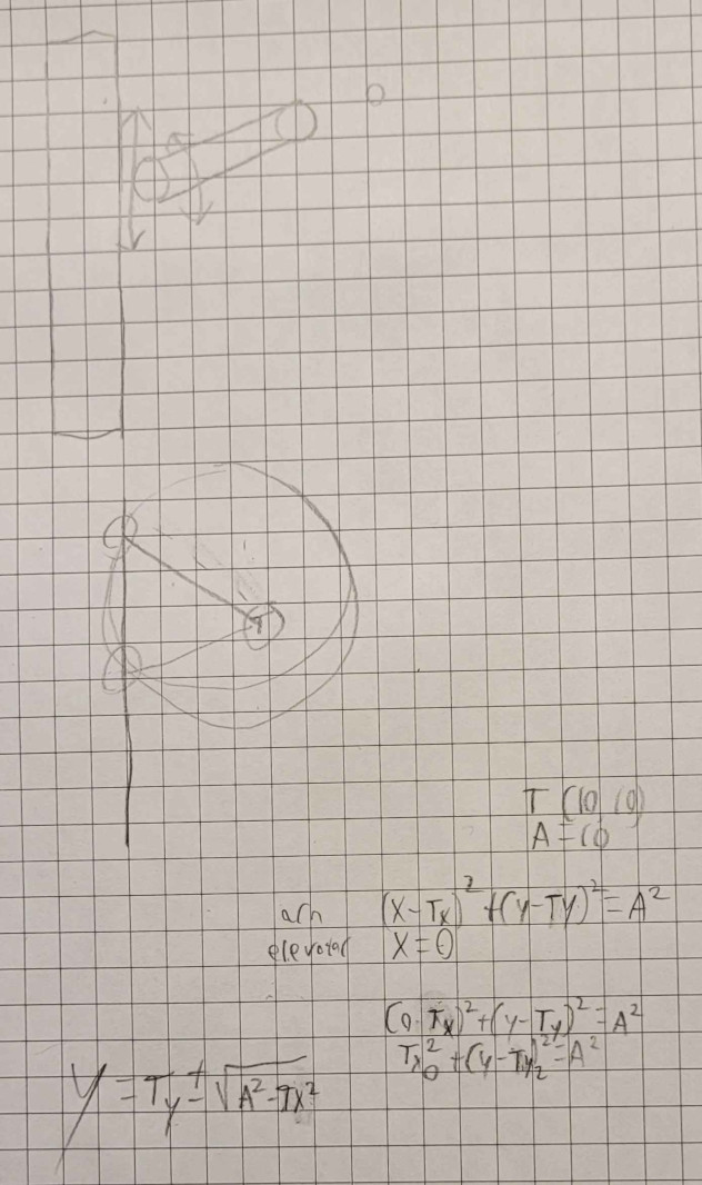
Inverse Kinematics#
Inverse kinematics is simply given and end position, find the combination of angles and heights to get to that position. I wrote out a simplified version of the problem on some graph paper and I realised that it is easier than is seemed. My idea was given a end point in 2d space, we can use the circle formula and sinc the elevator body is vertical, we can simply substitute into the circle formula.
Variables:
Tx= Target XTy= Target YAl= Arm LengthY= Arm Height
Equations:
- $$ (X - Tx)^2 + (Y - Ty)^2 = Al^2 $$
- $$ X = 0 $$
Solving for Y (arm Height):
After we have the height, we can check if the points or on the elevator or not. If one or more points are on the elevator, we can prefer the height that is closest to the current height. However, we have to take in consideration the trip along the top. Either way, we will end up with Y aka the height of the arm. To get the angle, we can use the following equation:
Variables:
Y= Arm HeightTy= Target YTx= Target XAa= Arm Angle
Equations:
- $$ Dx = Tx - 0 $$
- $$ Dy = Ty - Y $$
Solving for Aa (Arm Angle):
Here is my scratch work on paper:
Here is it in desmos: